| General Information |
| Applications |
| Loading the Sample |
| Clamping Torque |
| Axial Force Control |
| Equations |
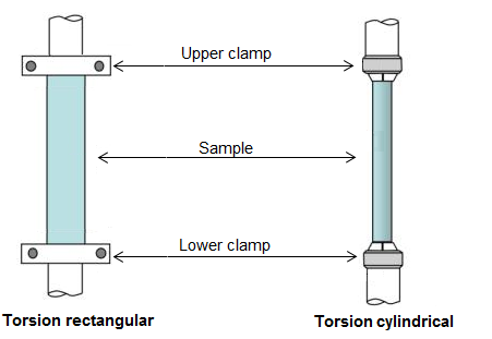
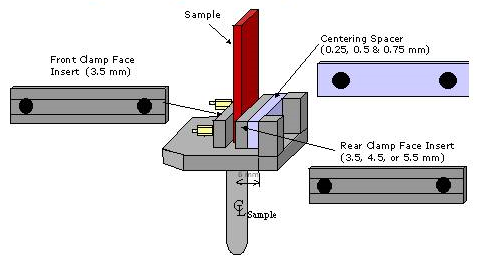
Torsion measurements are performed either on a rectangular-shaped or a cylinder-shaped sample. Torsion rectangular is the most used test method because sample preparation in compression molding is simple, and temperature equilibrium of the rectangular specimen is faster than for the cylindrical specimen. The disadvantage of the rectangular cross-section is that the constant stress lines are not linear and symmetric to the center of rotation. The maximum stress line is the centerline of the long side of the rectangle. De Saint Vénant was the first to describe the torsion of a non-symmetric test specimen. A schematic drawing of the torsion rectangular and torsion cylindrical test fixture is shown below. Solid or rubbery samples are preformed into rectangular bars and clamped with their long axis coaxial with the rheometer rotation axis. The ETC is used for samples to be run in air or inert gas. For submersion in water or aqueous solutions, a submersion cell is available for use with the Peltier concentric cylinder jacket.
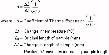
Two pair (upper and lower geometry) of jaws clamp the sample at both ends. In the torsion rectangular clamps, the sample is held between a spacer block and a clamping block; the clamping force is applied on both sides of the clamping block. In the torsion cylindrical, the sample is held top and bottom between appropriate size collets. Since the upper and lower geometry is separated by the long dimension of the sample, the expansion of the sample needs to be corrected for during temperature ramp tests to avoid sample buckling or stretching. The axial force adjustment mechanism compensates for sample expansion or contraction. Near the glass transition, the axial force needs to be controlled even more accurately to avoid undesired sample stretching or compression. Based on the sample length changes as a function of temperature, the coefficient of thermal expansion for the sample under test is also calculated according to:
The typical length of a torsion sample is between 10 mm and 40 mm. The width for rectangular samples is 10 mm to 12 mm. Stainless steel clamping blocks with spacers are used to accommodate various sample thicknesses and to center the rectangular sample.
For cylindrical samples three different diameter collets are provided (1.5, 3.0, 4.5 mm). Samples need to be prepared within ± 0.2 mm of the collect diameter.
The torsion geometry is used for testing solid materials such as thermoplastics, thermosets, composites, and elastomers below the glass or melt transition. The torsion geometry is used with the furnace (ETC) on DHR/AR Rheometers.
The rectangular torsion submersion clamp available for the DHR/AR is integrated into the Peltier fluid jacket for concentric cylinder systems (see DHR/AR Series Rheometers Getting Started Guide for details on installation and alignment).
When using the torsion submersion cell, follow the general guidelines below to load a torsion sample on the DHR/AR Rheometer. Although the samples used with the submersion clamps on the DHR/AR Rheometer have the same dimensional ranges as those used with the standard ETC solid sample clamps, the same loading procedure cannot be used because the clamping nuts cannot be tightened when the sample is in place in the cup. For this reason, the sample must be mounted in the clamps before being introduced to the cup. This means that, unlike those of the standard ETC, the upper and lower clamps of the submersion cell need to be aligned with the sample before installing the geometry. To allow this, the base of the submersion cup, which has the lower clamps integrally mounted, is removable and can be located centrally on top of the submersion cup. For gap setting and sample loading using the submersion clamps, follow the instructions given in the Wizards. The Zero Gap Wizard is activated by the zero gap routine and the Sample Loading Wizard is activated on the Instrument section of the ribbon by selecting load sample.
Lower the head until the sample can be fed into the upper collet, leaving enough sample to be clamped by the lower.
For torsion rectangular clamps, a torque screwdriver is included with the torsion geometry. For each material, some experimentation may be required to find the clamp torque that should be used. Under-tightening (or for softer materials, over-tightening) the clamps will result in erratic data. Once a torque value is established for a specific sample (material and thickness), all subsequent samples should be tightened to the same value. Both clamps should be tightened to the same torque value.
Samples are typically loaded at room temperature and then tested at various temperatures (i.e., temperature is varied in a temperature ramp test). It may be necessary to clamp the sample in the torsion geometry at the test starting temperature. Guidelines for clamping samples are provided below.
| Sample Type | Loading Guidelines |
| Soft thermoplastic above TQ at RT (for example PE, PP, PVDF) |
Load at RT and tighten to 40cN•m for DHR/AR. Apply axial force (see Axial Force Loading in the table below). Start the test. For subambient testing, set the initial temperature and allow the sample to equilibrate. Re-tighten clamps to 60 cN•m for DHR/AR. Start the test. |
| Stiff thermoplastic below TQ at RT (for example PC, PET, PS) |
Load at RT and tighten to 50 to 60 cN•m for DHR/AR. Apply axial force (see Axial Force Loading in the table below). Start the test. For subambient testing, set the initial temperature and allow the sample to equilibrate. Re-tighten clamps to 60 cN•m for DHR/AR. Start the test. |
| Elastomer above TQ at RT |
Load at RT and tighten finger tight. Apply axial force (see Axial Force Loading in the table below). Start the test. For subambient testing, set the initial temperature and allow the sample to equilibrate. Re-tighten clamps to 40 cN•m for DHR/AR. Start the test. |
| Stiff Thermoset below TQ at RT |
Load at RT and tighten to 60 cN•m for DHR/AR. Apply axial force (see Axial Force Loading in the table below). Start the test. For subambient testing, set the initial temperature and allow the sample to equilibrate. Re-tighten clamps to 60 cN•m for DHR/AR. Start the test. |
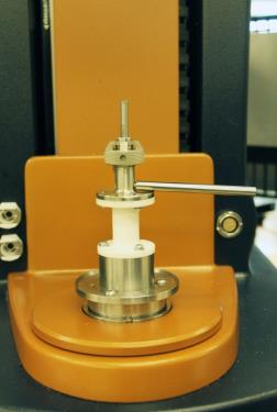
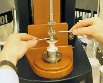
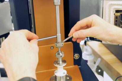
For cylindrical clamps the collets are tightened using the Tommy Bars as shown in the pictures below.
When the test temperature changes, it is critical to maintain axial force control on the sample. For example, if a temperature ramp test is run from low to high temperatures, then the sample and test geometries will undergo thermal expansion as the temperature changes. If the torsion geometries were held in a fixed position, then as the sample and the geometries expand, the sample would buckle. Sample buckling significantly interferes with calculations for the torsion geometry. To avoid buckling problems, always run torsion tests involving temperature changes with axial force control.
Axial force control allows the user to specify an axial force that is applied to a sample, as well as the allowable variation in the axial force (i.e., 1 N of axial force ± 0.1). The axial force can be specified to be either compressive or tensile. In the case of torsion tests, tensile axial forces are used. The following table provides recommendations for the axial/normal force settings. For additional information, see Axial Force Adjustment Guidelines.
| Sample Type | Axial Force | Axial Force Tolerance | Gap Change Limit Up | Gap Change Limit Down |
| Soft thermoplastic above TQ at RT (for example PE, PP, PVDF) | 2 N | 1.75 N | 2 mm | 5 mm |
| Stiff thermoplastic below TQ at RT (for example PC, PET, PS) | 2 N | 1.75 N | 2 mm | 5 mm |
| Elastomer above TQ at RT | 1 N | 0.5 N | 2 mm | 5 mm |
| Stiff Thermoset below TQ at RT | 5 N | 4 N | 2 mm | 5 mm |
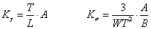
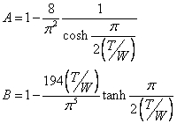
Geometry Factors for Rectangular Solid Samples
|
|
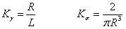
Geometry Factors for Cylindrical Samples
|
VariablesT = Rectangular sample thickness (mm) W = Rectangular sample width (mm) L = Rectangular or Cylindrical sample length (mm) R = Cylindrical sample radius (mm) |